Coil Winding Methods Explained
At Spang Engineered Solutions, we recognize that there is no one-size-fits-all approach to coil winding. Choosing the right method is critical to the performance, efficiency, and reliability of inductors and transformers. Our engineers carefully evaluate each project, considering coil geometry, production volume, electrical performance, and thermal management, to determine the optimal technique.
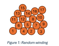
Random Winding
In random winding, magnet wire is wound in a disordered, scrambled pattern. This method is the lowest cost and fastest for large volume production of high-turn coils. The random nature of this technique can create areas of high voltage stress so it should be reserved for lower voltage applications.
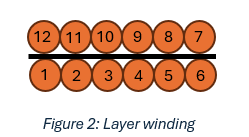
Layer Winding
In layer winding, magnet wire is wound in continuous layers with each layer stacked on top of the previous one. Layer insulation can be added between layers to increase isolation and enhance mechanical stability. Layer wound coils appear clean and uniform. This is often considered the “standard” winding technique.
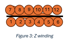
Z Winding
In Z-Winding, magnet wire is wound in layers with each layer stacked on top of the previous one, but at the end of each layer, the wire is dragged back to its initial starting position before proceeding. This forms a Z-shaped pattern and reduces capacitance and voltage stress by limiting the maximum electric field that can develop between layers. Layer insulation can be added between layers.
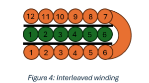
Interleaved Winding
Interleaved winding specifically applies to multi-coil components like transformers. Windings are divided and wound in alternating layers. For example, a primary winding that occupies two layers may be divided and the secondary winding placed between the two layers of the primary. The result is improved coupling between the windings which reduces leakage flux/inductance. This can also reduce proximity effects by minimizing magnetic field buildup between adjacent layers thus reducing AC resistance. The penalty of this winding technique is increased capacitive coupling between the interleaved windings which can worsen common-mode noise as well as increased manufacturing costs.
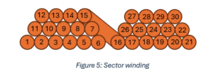
Section or Sector Winding
In section or sector winding, windings are divided into smaller sections. This can be applied to both single coil components and multi-coil components. In single coil components, this reduces capacitance and voltage stress by limiting the maximum electric field that can develop. In multi-coil components, this improves isolation between windings and reduces the capacitive coupling between windings.
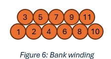
Bank Winding
In bank winding, the coil is wound in alternating directions. This is most typically applied on toroidal cores and is used to reduce capacitance and voltage stress by limiting the maximum electric field that can develop. The penalty of this winding technique is increased manufacturing costs.
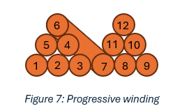
Progressive Winding
In progressive winding, the coil is wound in alternating directions (similar to bank winding) but the coil is divided into sections to form pie-shaped sections. This is sort of a hybrid of sector and bank winding deploying concepts from each. This is most typically applied on toroidal cores and is used to reduce capacitance and voltage stress by limiting the maximum electric field that can develop. The penalty of this winding technique is increased manufacturing costs.
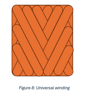
Universal/Basket-Weave Winding
In universal winding, the coil is wound with a pitch that alternates one or more times within a single turn. This alternating pitch allows the coil to be self-supporting and resembles the method in which twine is wound. It is typically used in conjunction with Litz wire to wind high frequency coils where capacitance must be minimized. The penalty of this winding technique is high manufacturing costs and custom tooling.